More Impact Testing
About 100 more impact tests with the air cannon have been done to test a few different types and methods of epoxy fills in order to improve the VIUD's shock resistance (more on that in a future blog post...soon). I've managed to successfully test speeds over 300 km/h (200 miles/hour) with impact shocks nearing 5000 G which seem to be the limit of what can be accomplished with the current shock testing rig for a couple of reasons.At lower speeds the air gun pressure was roughly linear with the output speed of the VIUD but exceeding 25 psi of pressure the output speed quickly flattens out (see the graph on the right). Since the theoretical terminal velocity of the VIUD is around 200 km/h (120 miles/hour) its going to be difficult to get it to go much faster than this. I may be able to get a little more speed out it by mounting the VIUD in a foam "bullet" to increase the firing efficiency but I don't know exactly how much that will get me.

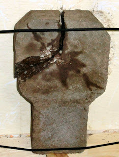
Stone Targets Destroyed by VIUD Impact Tests
Against the heavier and tougher Titanium VIUD at speeds above 200 km/h (120 miles/hour) a new stone target (left image above) broke after just 4 impact tests. I've since started using a thicker 2" Arkansas Limestone target which is a bit softer but seems to take the hits a bit better.
I also seem to have reached a measurement limit with the high-speed camera. The Casio Exilim EX-ZR200 was the cheapest camera I could find that could go up to 1000 fps. This is much faster than most cameras but this speed seems to limit the measured impact accelerations to under 5000 G. At this magnitude the actual impact occurs in well under one frame (<< 1 ms) so it is likely underestimating the actual impact force. I'd love to get a better camera that can do at least 10k fps or better but the ones I've looked at are quite pricey.
Aluminum Case Preparation
Before I can get the remainder of the Aluminum cases anodized there is a fair amount of preparation work needed. In truth, they could probably be anodized as they are and turn out OK but I'd prefer to take a little bit of time and make them better than just "OK".First step was to make a simple jig that can hold the VIUD cap or base securely, quickly, and accurately in the lathe without damaging them. It was relatively straightforward to design and manufacture an Aluminum collet piece sized exactly to the outer diameter of the VIUD.
 |
| Simple Jig for Holding a VIUD Cap/Base in the Lathe |
Using this jig I increased the size of the cosmetic chamfer on the ends of the cap and base from essentially 0.00" (it was barely what you could call a "broken" edge) to 0.01". While this seems like an insignificant modification it stops this edge from feeling sharp and will help the anodizing from chipping prematurely.
Next step is to polish all remaining Aluminum 150 caps and bases. The finished surface as they are is typical dull Aluminum. By polishing to a near mirror finish the resulting anodized surface will be much shinier and it also helps break any remaining sharp edges for a better feel as well as preventing the anodized surface from chipping.
 |
| Comparing Original (Left) and Polished (Right) Aluminum VIUD Bodies |


No comments:
Post a Comment