Showing posts with label testing. Show all posts

Wednesday, February 19, 2020

Burn-In Speed Testing

A prospective VIUD buyer recently asked me this question:
How well are the read/write times in comparison to market stock times? I have a SanDisk, but for the life of me they don't post read times, and it slows down in the middle of large projects. ... When it gets hot my progress slows down by a whole addition hour.
An interesting question that I didn't have the exact answer to. I've done a lot of basic, short-term speed testing and a couple of very long (weeks) burn-in tests for error checking, but no tests to see if the USB speed varied over a long term or to measure how hot the VIUD gets.

Testing

The basic setup was to just continually write to a VIUD over a period of about a day (continually copy a 4GB file to the drive) and do a couple of speed tests over that period to see if there was any variation. The continuous writing to the drive was paused while the speed tests were performed.

Since the original question may be related to drive temperature I also measured the temperature of the case. The tests were done for both an Aluminum (32GB) and Titanium (256GB) drive.

Results

Results are shown the below tables.

Time Case Temp Read Speed Write Speed
0 hr
23°C
155.4 MB/s
98.1 MB/s
0.5 hr
27°C


2.5 hrs
33°C


5.7 hrs
35°C


8.5 hrs
37°C
157.0 MB/s
89.2 MB/s
21.3 hrs
37°C
156.8 MB/s
89.3 MB/s
28.3 hrs
36°C
155.1 MB/s
87.2 MB/s
Burn-In Speed Test for Titanium 256GB VIUD

TimeCase TempRead SpeedWrite Speed
0 hr
22°C
142.1 MB/s
28.5 MB/s
4.2 hrs
30°C
142.9 MB/s
28.6 MB/s
17.5 hrs
28°C
143.5 MB/s
28.3 MB/s
27.3 hrs
29°C
141.2 MB/s
18.1 MB/s
Burn-In Speed Test for Aluminum 32GB VIUD

In read/write speeds are the sequential speeds obtained from the CrystalDiskMark benchmarks. While there is some variation in the read tests it is within what we would expect the normal variation to be. The write tests show a small drop (9%) in the write speed for the Titanium drive. For the Aluminum drive the last write speed test shows a significant (36%) drop in write speed although I'm not sure I believe that data point or not as the HD Tune Pro results showed no significant speed decrease in any test for either VIUD.

For the temperature testing the ambient temperature was around 20°C for all tests. The temperature was measured where it was the highest value on the drive which tended to be the USB connector.

I also did some quick tests on a Sandisk Extreme 16GB USB drive. Temperatures were similar to the Titanium VIUD and no speed degradation was observed.

In terms of qualitative results, the Titanium VIUD gets very warm but not uncomfortable to the touch, similar to a normal USB drive. The Aluminum VIUD gets just a little warm to the touch.


Theory

The potential reason a typical consumer USB drive might overheat and a VIUD might not can be explained by looking at the thermal conductivities of the relevant materials.

Material Thermal Conductivity
Air
0.025 W/mK
Epoxy
0.3 W/mK
Titanium
20 W/mK
Aluminum
205 W/mK

In a consumer USB drive the circuit board is surrounded by air trapped inside the case which has a very low thermal conductivity thus trapping the heat near the board and causing to it to reach a high temperature. In a VIUD drive the circuit board is surrounded by epoxy which has 10x the thermal conductivity than air which enables it to direct the heat away from the board and into the metal case and air. In addition, the VIUD drive has the USB metal connector in close contact to the metal plug which further helps conduct the heat away from the USB.

Discussion

Compared to a normal USB the Titanium VIUD reached a similar temperature on the USB metal connector (37°C). How this translates to the interior circuit board temperature is unknown...we would expect the epoxy encased VIUD to be somewhat cooler than an air encased USB but by exactly how much would require more advanced temperature modeling.

The Aluminum VIUD was noticeably cooler on the USB metal connector (30°C) and would be the choice if long term reading/writing and overheating of the USB was a concern.

Thursday, March 5, 2015

Evaluating New Case Manufacturers

In the last post I mentioned finding four new case manufacturers for the VIUD and having a few samples made from each one. To choose one manufacturer for a larger case order we'll have to evaluate/test the samples and pick one that has the best combination of quality and price.


Machining Quality

The easiest test we can do for the case samples is to simply make sure we received what we asked for. We'll measure all the dimensions from the three case pieces (base, cap, and plug) and compare that with the drawing specification for all four manufacturers:


ItemManufacturer AManufacturer BManufacturer CManufacturer D
Dimensions OK
16 / 32
30 / 32
31 / 32
31 / 32
Dimensions Not OK
8
2
1
1
Dimensions Way Off!
8
0
0
0
Finish
Al - Poor Clear Anodized
Ti - Black?
Al - Natural
Ti - Natural
Al - Clear Anodized
Ti - Natural
Al - Anodized Black
Ti - Natural
Assembly
Threads Don't Fit
OK
OK
OK
Cap chamfer for o-ring too small

Manufacturers B, C, and D all fair well with only a couple minor deviations outside of the expected dimension tolerances (mainly a couple chamfers that were a bit smaller than desired). Manufacturer A, on the other hand, was so bad I had to create a special category just for it. Half of the dimensions were outside of tolerances and some features were outright missing. The threads, or I should say the attempt of threads, were a wonder to behold. All the inside threads were double-started, the screw angles of the exterior threads were wrong and skewed to one side and at least one thread was not square to the body by more than 5°
. Even a considerable attempt to restore the threads with a tap and file failed to get them working fully. It is fair to say that Manufacturer A won't be further considered even though they did ship first and didn't charge me anything (I wonder why).


Appearance

The quantitative dimension comparison showed Manufacturers B, C, and D to be very close with each other but how about a more qualitative "appearance" test? Although accurate dimensions are important the case has to look good as well. We can rate a few different appearance factors for each manufacturer:


ItemManufacturer AManufacturer BManufacturer CManufacturer D
Surface Finish
Very Poor
Very Good
Excellent
Very Good
Knurl Quality
Very Poor
Good
Very Good
Very Good
Assembly Fit
Doesn't Assemble!
Very Good
Good
Acceptable
Overall Appearance
Very Poor
Good
Excellent
Very Good

Ignoring the terrible performance from Manufacturer A, the other three look equally well with C and D slightly leading the pack.


Stress Testing

The final test will be a destructive stress test to failure. The purpose of this test is to determine the type and quality of material used. While I specified very specific alloys (Al 7075-T6 and Ti Grade 5) it is difficult to tell the exact alloy used. It is possible they used a much cheaper alloy (like Al 6061 or Ti Grade 2) or mistakenly used an untempered Aluminum alloy like 7075 instead of 7075-T6. The only way I know to test the alloy, other than a spectrograph, is a stress test to see at what load the item fails.

This will be the first destructive stress test in a long while...the last one was actually the first brass prototype almost two years ago. I've been meaning to destructively test a few from the prototype #5 pre-production test but I have too many non-destructive tests still to do. These tests will validate, or not, the theoretical stress modelling I've done in Autodesk Inventor.


The stress tests will use an assembled unit without any epoxy or USB board. We'll start with the end-to-end stress test in my hydraulic shop press and finish with a side stress test if the unit survives. Note that a value of "> 9 tons" in the following table indicates it didn't fail in the test.


Stress TestExpected FailureManufacturer AManufacturer BManufacturer CManufacturer D
Al : End-To-End
6.5 tons
6.5 tons
6 tons
> 9 tons
> 9 tons
Ti : End-To-End
9 tons
> 9 tons
> 9 tons
> 9 tons
> 9 tons
Al : Side
4 tons
4 tons
4.5 tons
6.5 tons
7 tons
Ti : Side
6 tons
> 9 tons
8 tons
> 9 tons
> 9 tons

The complete video of the stress testing is also available:


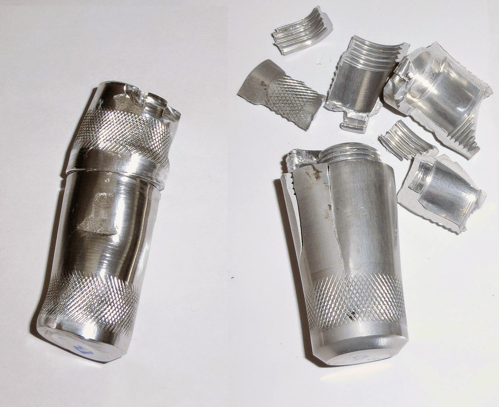
From the stress failure loads and the way the case failed I would say that Manufacturers A and B used a lower strength Aluminum alloy like untempered 7075 or 6061 while Manufacturers C and D used the 7075-T6 alloy as specified. Both A and B failed in a ductile manner (the case deformed slowly and remained in one piece) while both C and D cracked suddenly (see image below). This sudden cracking is typical of a stronger alloy like 7075-T6 or 7068 which are more brittle than other Aluminum alloys. 


Comparison of Failures in Lower Strength Aluminum Alloy (Left) and Higher Strength (Right)

Another interesting thing to note is that the cases C and D outperformed the theoretical failure loads by a good margin, at least 50%. The cases failed pretty much where they were expected to fail (cap threads for the end-to-end test) and there were no big surprises. The hole for the lanyard mount did fail in the end-to-end stress test on two cases at high loads but this was expected to happen at some point and the failures were not premature.


Which One?

Considering all case evaluations and tests Manufacturers C and D come out notably ahead of the other two. Manufacturer C has a low lead time but higher price while Manufacturer D has a very long lead time but the cheapest price by a considerable margin. My choice for the first large order will be Manufacturer D, mostly due to the price, but I'll keep C in mind as a backup.


Monday, October 6, 2014

Can you do this with your USB Drive (Part 2)?

A short video on something you shouldn't do with just any USB drive. See it below or directly on YouTube.

Friday, October 3, 2014

Shock Testing Video

The next VIUD  video on shock, or acceleration, testing is now available! See it below or directly on YouTube.


Also look on our YouTube Channel for some hi-speed shock testing videos like this one:


Thursday, October 2, 2014

Can you do this with your USB drive?

A quick demonstration of how tough the VIUD really is by holding it in my bare hand while in a 2000 °C flame for 30 seconds! See it below or directly on YouTube.


Wednesday, October 1, 2014

High Temperature Testing

The next VIUD testing video on high temperatures is now available! See it below or directly on YouTube.


Keep tuned for more testing videos soon!

Monday, September 29, 2014

Pressure Testing Video

My first VIUD video on pressure testing is up! See it below or directly on YouTube.


Now that I'm getting the hang of video recording and editing look for more testing related videos in the next few weeks!

Sunday, September 22, 2013

Shock Testing, Round #1

One of the required ratings for our rugged VIUD is shock or acceleration and so we will need to build a test rig for this purpose. There are basically two ways of measuring the acceleration an object undergoes:
  1. Install accelerometers on the object and measure the acceleration directly.
  2. Take high-speed video of the object and indirectly measure the acceleration.

Our VIUD is far too small to install accelerometers on it which leaves us with the only other choice. 


High-Speed Video Camera

Using high-speed video necessitates buying a capable video camera but after much searching it seems that all of the dedicated high-speed cameras are far out of my price range of a few $100. Most vendors never list prices on their websites and instead say "Contact Us for Quote" which is just code for "really expensive", at least many $1000s if not $10,000s. 

Fortunately, after some further research I found out that Casio has a line of consumer cameras, the High Speed Exilim models, that support high speed video capture. Some models, including the ZR200, support frame rates up to 1000 fps at a resolution of 224x64 pixels: small in size but hopefully fast enough for our purposes. The price of around $220 is also nice although I hit a small issue when trying to purchase the camera: Casio doesn't sell their cameras at all in Canada. Fortunately I was able to eventually find a vendor in Japan that would sell me one (a lot of American vendors in general don't ship outside the USA).

An example video from one of the first few shock tests is below (prototype #3 at an impact velocity of 130 km/hr) :


The low resolution is immediately apparent but it is still usable for our purposes. Not surprisingly it takes pretty brightly lite environment to get a good video image at 1000 fps. The black & white pattern in the background is a scale (5 cm per large band) to give us the real world measurements within the video. More shock testing videos can be seen in our VIUD YouTube channel.

Shock Test Rig

The idea for the shock test rig is to make a custom air gun that fires the VIUD at a desired rate of speed at some target. The basic design of an air gun is pretty simple:
  • Barrel for firing the projectile
  • Valve to fire the gun
  • Source of air under pressure

Unfortunately, my first naive attempt failed wonderfully: I simply hooked up an air compressor to a 1/2" ball valve attached to a 4 ft length of 1" pipe. Technically you could say it works if you considering "working" as barely being able to push the VIUD out of the barrel. The air compressor and its 1/4" hose simply can't supply the air fast enough into the barrel to give the projectile enough velocity.

The air gun design needs to be changed to hold a volume of compressed air close to the barrel with the largest possible pipe diameter connecting them (ideally the same size as the barrel if not larger). I first considered using a length of 2" or larger pipe but could not easily source the material locally. The next option considered was a small portable air tank. Initially this seemed like it would not work as all air tanks I looked at used a small 1/4" hose but on closer inspection the actual connection into the tank was a larger 1/2" NPT which is hopefully large enough to give our air gun some punch. I was also lucky enough to find a 5 gallon air tank on sale at my favourite store Princess Auto for only $25. I must confess to purchasing much more than just the air tank during my visit there (a very dangerous place to visit).

With a better design the assembly is relatively simple and uses all off-the-shelf parts available at any large hardware store. Total cost of everything to make the air gun was under $150 not counting the air compressor which I already had.


The Finished Air Gun for Shock Testing

The basic parts and features as shown in the above image are as follows:
  • Barrel - 4 ft, 1" pipe with Copper pipe insert
  • Firing Device - 1" Ball Valve 
  • Air Chamber - 5 gallon tank with a 1/2" NPT connection
  • Air Source - Electric air compressor 
  • Control - Pressure gauge, regulator valve and shut off valve

I added a Copper pipe into the original barrel mainly to provide a smoother surface: the inside of the steel pipe was very rough and was scratching up the VIUD pretty badly during the first few runs. It also served to narrow the barrel's ID a little bit resulting in around 30% higher velocities at a given air pressure.

After a few trial runs it was obvious that the shock testing rig design works very well. Projectile velocity even at the lowest pressure setting of 15 psi is around 110 km/hr (60 m/hr) which is fast enough to be a little scary. This should be more than enough to reach the VIUD's terminal velocity of 55 m/s (200 km/hr, 120 m/hr) and beyond should we need it.


Measuring Acceleration

With our shock testing rig and high-speed video camera we're all set with the exception of having to figure out exactly how to measure our VIUD's acceleration from the video. My first attempt was to simply save individual frames from the movie, paste them into Inkscape (a 2D drawing editor), measure the movement and somehow convert that into an acceleration. This was very tedious and didn't work well at all so it wasn't long before I was searching the Internet for an alternative.

It was a quick search as the first Google result led me to an article about measuring the acceleration of a jumping Arboreal Lizard and that quickly led me to Tracker, a free application used for measuring velocities and accelerations from videos. The interface is a little wonky (some things just stop working randomly) and the documentation is mostly the "figure it out yourself" type but it does exactly what I need and was pretty easy to pick up its basic usage.
Tracker: A Free Video Analysis and Modelling Tool for Physics Education

Shock Testing

The procedure for shock testing is pretty straight forward:
  1. Choose an air pressure (higher pressure for higher exit speeds)
  2. Choose a target type (wood, stone, etc...)
  3. Record the impact using the high-speed camera
  4. Analyse the video using Tracker to determine the speed and acceleration
  5. Test the USB to ensure it still works (basic error checking and bit change tests)

Using one of the third prototypes for testing we have the following results so far:

PressureTargetSpeedMax AccelerationTests PassedNotes
15 psi
Wood
80 km/hr
900-1000 g
Passed
Minor scratches from inside of barrel
15 psi
Wood
80 km/hr
1100 g
Passed
15 psi
Wood
80 km/hr
1200 g
Passed

20 psi
Wood
110 km/hr
1500 g
Passed
25 psi
Wood
130 km/hr
1800 g
Passed
15 psi
Wood
100 km/hr
1300-1500 g
Passed
Added internal Copper sleeve to barrel
15 psi
Stone
100 km/hr
1500 g
Passed
20 psi
Wood
125 km/hr
1900 g
Passed
25 psi
Wood
150 km/hr
2100 g
Passed
25 psi
Wood
145 km/hr
2000 g
Passed
30 psi
Wood
160 km/hr
2100 g
Passed
35 psi
Wood
180 km/hr
2500 g
Passed
40 psi
Wood
190 km/hr
1900 g
Passed
Broke the wood target!

So far the VIUD passes all shock tests with flying colours which is good news indeed. One surprising thing is the large accelerations involved. Even with video at 1000 fps the impact occurs in less than one frame which means that even these large accelerations may well be underestimates. This also makes it difficult or impossible to distinguish the difference between target materials. In theory a stone target should result in considerable more deceleration than a wood target but we would probably need a 10,000 fps or higher video camera to discern the difference.

Amazingly the last test broke all three layers of the 2" thick wood target. The first 1/2" MDF layer broke completely through likely due to the combined effect of all previous tests. The next two 3/4" Pine layers broke into multiple pieces along their grain. Looks like I'll need to make a sturdier target, probably out of multiple layers of MDF, hardwood and plywood.


Broken 2" Thick Wood Target After a Dozen Shock Tests (Side View on the Right)

An interesting note is that the few rugged USB competitors that do explicit shock ratings are only rated at 40-50 g which means our shock ratings exceed theirs by an amazing factor of 50!


Friday, September 6, 2013

Temperature Testing, Round One

So far we haven't done any temperature testing other than the failed attempt with the first prototype and a propane torch which melted the USB connector's plastic. Our investigation into being the toughest USB drive in the world showed that a good temperature rating is one thing we are currently lacking.

We will perform some initial temperature testing with the one of the third prototypes which has been destined for eventual destructive testing, although we will try to be careful and not destroy it so we can get as much data from it as possible.


Failure Modes

Before going ahead with the testing it may be useful to review exactly how our VIUD may fail at high temperatures:

  • Plastic in USB connector melts
  • USB flash drive fails
  • O-rings Melt
  • Internal epoxy melts/fails
  • Body melts
The primary failure modes we're interested in would be the first two. The plastic melting in particular is the most likely failure as, depending on the exact type of plastic, it occurs at relatively low temperatures of 150-315 °C (300-600 °F)  although Wikipedia states a melting temperature for Polyethylene as low as 105 °C (220 °F).

It is difficult to determine at what temperature the flash memory will fail at although it appears to be a gradual process: the higher the temperature the more likely bits will flip by themselves. There is an interesting paper that shows results for accelerated temperature testing in the range of 170-250 °C (340-480 °F) and gives the data retention for their device at 105 °C (220 °F) as 10 years. We can assume from this that the failure temperature for the flash memory is also relatively high and not likely to occur before the connector plastic melts.

Similarly the last three failure mechanisms occur at temperatures above that of the plastic melting point. If Viton o-rings are used they are rated to 200 °C (390 °F) and probably won't completely fail somewhere above that. The epoxy used in this prototype is only rated to 125 °C (260 °F) but again won't completely fail somewhere beyond this temperature and the actual epoxy that is going to used is rated much higher (300 °C, 570 °F). The melting of Aluminum (660 °C, 1220 °F) and Titanium (1670 °C, 3030 °F)  is so high as to be mostly irrelevant.


Procedure

The procedure for temperature testing will be relatively simple:
  1. Let test object return to room temperature.
  2. Let test apparatus achieve desired temperature (if applicable).
  3. Subject test object to the desired temperature for a set amount of time.
  4. Cool object after test in water for at least 5 minutes.
  5. Examine object for any obvious signs of damage.
  6. Test USB for any new file blocks with errors.
  7. Test USB contents for any changes in data.
  8. Repeat test at slightly higher temperature and/or longer period as desired.
The test for bad blocks is done using HD Tune Pro which is a basic drive benchmark and tester. The test for changing bytes during a test is simply done by creating random files that fill the USB and using a MD5 sum to ensure their contents are identical before and after the test.

Test Results

The following table summarizes all the temperature test results so far:


Test TypeTemperatureLength of TimeError TestBit Change TestNotes
Oven
90 °C (200 °F)
5 min
PassedPassed
Oven
120 °C (250 °F)
5 min
PassedPassed
Oven
150 °C (300 °F)
5 min
PassedPassed
Oven
180 °C (350 °F)
5 min
PassedPassed
Oven
200 °C (400 °F)
5 min
PassedPassed
Oven
230 °C (450 °F)
5 min
PassedPassed
Oven
260 °C (500 °F)
5 min
PassedPassed
Oven
290 °C (550 °F)
5 min
PassedPassedCase exterior exceeds 100 °C
Oven
290 °C (550 °F)
6 min
PassedPassed
Oven
290 °C (550 °F)
7 min
PassedPassed
Oven
290 °C (550 °F)
8 min
PassedPassed
Propane Torch
1800 °C (3300 °F)
10 secs
PassedPassed
Propane Torch
1800 °C (3300 °F)
20 secs
PassedPassed
Propane Torch
1800 °C (3300 °F)
30 secs
PassedPassedCase exterior exceeds 100 °C
Propane Torch
1800 °C (3300 °F)
40 secs
PassedPassedMinor damage to external o-ring
Propane Torch
1800 °C (3300 °F)
2 min
FailedFailedPrototype #1, USB plastic melted
Oven
200 °C (400 °F)
15 min
PassedPassed
Oven
290 °C (550 °F)
9 min
PassedPassed
Oven
290 °C (550 °F)
10 min
PassedPassed
Boiling Water
100 °C (212 °F)
60 min
PassedPassedTurned Aluminum black
Wood Fire
600 °C (1100 °F)
30 sec
PassedPassedCase exterior exceeds 100 °C
Wood Fire
600 °C (1100 °F)
45 sec
PassedPassedDamage to external o-ring
Wood Fire
600 °C (1100 °F)
60 secs
PassedPassedDamage to external o-ring

One interesting thing to note is that the boiling water test turned the drive a black color with tints of gold that actually looks rather nice (resembles a black anodized Aluminum). I'm assuming it is something in my water (a very hard water) that turned it this color.
Surprise...it's Black Now!

Comparing the Competition

Most USB drives don't have explicit temperature ratings but of those that do the LaCie Xtremkey has the highest:
  • Operating temp.: 5 to 35°C (41 to 95°F)
  • Non-operating temp.: -20 to 60°C (-4 to 140°F)
  • Fire test: 30 sec. fire exposure
  • Heat test: 200°C (392°F) / 3 min
Since we easily beat both of the listed tests by a considerably margin it is safe to say our VIUD would be the toughest USB drive available for temperature ratings.

Tentative Ratings

We still have to test our final design although I wouldn't expect too different results with the possible exception of the Titanium model performing a little better. We can still estimate our temperature ratings based on the tests so far:
  • Operating Temperature: ? to 60 °C (? to 140 °F)
  • Storage Temperature: ? to 90 °C (? to 200 °F)
  • Air Storage: 290 °C (550 °F) for 5 minutes
  • Boiling Water: 100 °C (212 °F) Indefinitely
  • Wood Fire: 1 minute exposure (600 °C, 1100 °F)
  • Propane Torch: 40 seconds exposure (1800 °C, 3300 °F)
The operating and storage temperatures may be changed by the specifications of the USB flash memory used. Next up will be testing the cold side of the temperature scale which should be interesting to see how low we can go.


Thursday, August 29, 2013

The Toughest USB Drive in the World

I was thinking last night while I was trying to fall asleep about the following question:

What do I need to do to honestly be able to call the VIUD the world's toughest USB drive?

While I think we're already pretty close to this point we'll look at a few areas that a USB drive needs to excel at to be called "tough":

  1. Pressure
  2. Temperature
  3. Acceleration / Shock
  4. Force / Load

The pressure rating is an immediate win for our VIUD: currently rated at 3000 psi it is at least ten times higher than any other USB drive out there except for the old Tyukalov which was rated at 2000 psi.

So far we haven't done any temperature tests except the failed 2 minutes at 1100 °C propane torch test on prototype #1. Most USB drives don't have explicit temperature ratings or they are simply set incredibly low but the LaCie Xtremkey is rated for 3 minutes at 200 °C and 30 seconds fire exposure. I hope I can beat both these ratings despite using essentially off-the-shelf USB drives since the failure mechanism is the plastic in the USB connector melting.

Most drives are also not rated for shock/acceleration with the Xtremkey again topping the chart with a rating of 50G. I haven't done any shock testing yet although the high-speed camera has been ordered and some basic calculations seem to indicate that a 50G rating should be easily beaten.

The force/load tests are really the most important ones for a "tough" USB drive and there are actually no drives out there with explicit force or load ratings. There are a few with unofficial "car/SUV drive over rating" but this is actually a relatively low bar to pass. Even a large moving truck driving over a USB only exerts around 2 tons of force which even our low strength brass prototype could withstand. Stress modelling of our Aluminum and Titanium VIUD design shows a worst case failure in end-to-end stress to be in the area of 8-10 tons. This would seem to point towards a win this category although actual destructive stress testing of competing drives will have to be done to be sure.

So while the prospecst look very good that we will be able to call our VIUD the "world's toughest USB drive" we have a bunch of testing to do first.


Thursday, August 22, 2013

The First Prototype

Now that we've done our basic design and research for our rugged USB drive it's time to start making something! I'm a very amateur machinist and the basic design for the drive case is simple enough for me to attempt to make, at least for the testing prototypes. 

I choose Brass for the first prototype's material for a number of reasons: 


Brass Pros
  • Easy to machine
  • Cheap
  • Shiny!
Brass Cons
  • Mechanically Weak
  • Heavy


This is fine for a simple prototype but the Brass cons are more than enough to consider other materials for the final product (materials are to be discussed in a future blog entry).

The design of the VIUD case is relatively simple and is composed of three parts:

  1. Cap - Removable part that covers the USB connector and attached with thread.
  2. Base - Main body of the USB 
  3. Plug - Threaded plug which the USB fits into and is permanently mounted into the base.
Basic Components of our VIUD Design

Machining these parts is relatively simple, even for an amateur, although there are a few "gotchas" to note:
  • Using a tap to manually create the threads is difficult at best. You have to tap before machining the case OD or else the body walls buckle outwards. 
  • It is difficult/impossible to create a perfectly straight thread with manually tapping (even with a jig) which causes the cap to not sit perfectly on the body. This can be corrected by filing the edge of the cap but is tedious. 
  • The hole in the plug for the USB connector is machined with round corners and needs to be filed out square.
  • The groove in the plug for the main o-ring seal was done after assembly and the epoxy had hardened to ensure a perfect fit.
  • The mount for the cap at the end of the base was added afterwards by press fitting an additional piece into the base.
For the USB flash drive itself I merely purchased a cheap 2GB consumer level drive and removed the plastic case. Assembly merely required to insert the USB into the rear side of the plug, fill the base with epoxy (enough to squeeze out when assembled) and screw the plug into the base. After letting the epoxy dry and machining a groove for the o-ring seal in the plug the first prototype VIUD is finished! Unfortunately I don't have any pictures of the prototype before its destruction in stress testing.

Testing

End-to-End Stress Modelling
Our first VIUD prototype may not look too pretty but it is fine for basic testing of our design. First is a simple handling test: How does the drive feel in terms of weight and size. The size feels fine although it is significantly larger than most USB flash drives these days. It is a little on the heavy side, however, at around 150 g. Not terrible but a little too noticeable when held in your pocket. The overall physical operation of the drive is also fine and doesn't reveal any unforeseen difficulties.

Next, with our simple and cheap pressure testing rig we can easily see what pressure our prototype can handle. Fortunately, even with a slightly crooked cap it successfully passed a 1 hour test at 3000 psi with no leaks! 

Temperature testing was next and I was evidently a little too eager at this stage by using a propane blow torch. Even with just a 2 minute external exposure of 1100 °C the plastic in the USB connector melted completely and a quick repair attempt failed to get the USB drive to respond when plugged in to a computer.

Since the drive was already toast the next and final test was the destructive stress test. I purchased a basic 10 ton hydraulic press from my favourite store Princess Auto. I had done some basic stress modelling using Solidworks and Autocad Inventor which showed the failure of the Brass prototype should occur at around 4000-5000 lbs on the threads of the cap with a vertical load. The modelling proved very accurate as that is exactly when and where the prototype failed! We usually assume modelling is reasonably accurate but it is always nice to see it verified once and a while.

Brass VIUD Prototype #1 -- After Destructive Testing

Lessons Learned

Despite the first prototype being destroyed during testing it yielded a number of important insights:
  • Validated the overall design.
  • Handling pressures up to 3000 psi should be no issue.
  • Brass is too heavy and too soft a material for a true VIUD.
  • Manually trying to tap the threads myself doesn't work very well.
  • The mechanical stress modelling agrees very well with the actual stress testing.
  • Temperature testing will have to be done a little more carefully (no propane torch)!
More prototypes, testing and research await for us on our quest for the ultimate VIUD....